Quantity
|
Out of stock
|
||
|
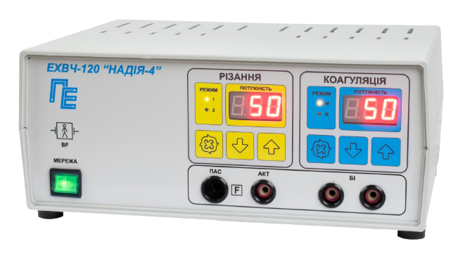
High‑Frequency Electrosurgical Unit HFE‑120 "Nadiya‑4"
This unit is designed for cutting and coagulating soft tissues and blood vessels using high‑frequency current without anesthesia during surgical procedures in hospitals and clinics.
The device is intended for use in specially equipped rooms at ambient air temperatures between 10 °C and 35 °C and relative humidity up to 80 % at 25 °C ambient temperature.
Principle of Operation
The unit serves as a high‑frequency current source. HF voltage is applied to the active and passive (monopolar) electrodes, or to a bipolar forceps (electrode), and delivered to the patient’s tissue. The electrosurgical cutting and coagulation effect is achieved by delivering sufficient thermal energy through a narrow HF‑current flow at the point of contact between the active electrode or between the tips of bipolar forceps and the tissue. In monopolar mode (CUT‑1, CUT‑2, COAG‑M), the active electrode is significantly smaller than the passive electrode, resulting in higher current density in the tissue near the active electrode. When power is sufficient, tissue fluid vaporizes and causes cutting. In bipolar mode (COAG‑B), both forceps tips act as active electrodes located close together, generating HF current between them, which heats tissue and causes coagulation through protein denaturation.
Technical Data and Additional Features
The unit supports the following modes: standby, cutting, and coagulation, with specific configurations for:
Cutting Modes:
- CUT‑1 – monopolar, continuous HF output after activation.
- CUT‑2 – monopolar, amplitude‑modulated pulsed HF output after activation.
Coagulation Modes:
- COAG‑M – monopolar, continuous HF output after activation.
- COAG‑B – bipolar, continuous HF output after activation.
Output power is adjustable in discrete steps across all modes.
Device Capabilities:
- Operate in idle and short‑circuit conditions at any power level;
- Optical indicators:
- Power supply active – green light;
- Selected mode – yellow “CUT” indicator or yellow-on-blue “COAG” indicator;
- Output power level – red indicator on colored background (yellow or blue);
- Passive electrode cable disconnection – red “Err PE” display.
- Audible frequency‑timbral signals:
- CUT mode – continuous tone; COAG mode – single intermittent tone;
- Passive electrode cable disconnection – double intermittent tone.
- 8‑hour operation at maximum output for repeated‑short‑time cycles: 10 s ON, 30 s OFF;
- The unit may remain continuously powered for no more than 8 hours.
The unit is protected against defibrillator discharge effects.
Equipment Composition and Delivery Kit
- Electronic unit AAOX.941612.004SB;
- Foot pedal AAOX.642139.001;
- Passive electrode;
- Monopolar electrode holder;
- Monopolar electrode set;
- Bipolar electrode holder;
- Bipolar forceps;
- Manual AAOX.941612.004PS;
- Packing AAOX.305636.001.
Unit Design
The unit consists of two separate parts: the electronic unit and the foot pedal.
Front Panel of the Electronic Unit |
![]() |
1. Manufacturer logo.
2. Model name.
3. Indicator for CUT‑2 (mixed mode).
4. Indicator for CUT‑1.
5. Digital output power display for CUT.
6. Indicator for COAG‑B (bipolar coagulation).
7. Indicator for COAG‑M (monopolar coagulation).
8. Digital output power display for COAG.
9. Power-up button for COAG.
10. Power-down button for COAG.
11. Sockets for bipolar forceps cable.
12. COAG mode switch.
13. Power-up button for CUT.
14. Socket for active electrode cable.
15. Power-down button for CUT.
16. Active electrode area marking.
17. Socket for passive electrode cable.
18. CUT mode switch.
19. BF‑type insulation symbol and defibrillator protection.
20. Mains power switch.
Rear Panel of the Electronic Unit |
![]() |
21. Foot pedal socket.
22. Class II electrical safety symbol.
23. Power cable.
The electronic unit is housed in a plastic case with top/bottom covers and front/back panels. The front panel includes:
- Power switch and indicator “POWER”;
- Mode switch buttons (12, 18) with corresponding indicators: CUT‑1, CUT‑2, COAG‑M, COAG‑B (3,4,6,7);
- Output power adjustment buttons (9,10,13,15) with power level displays (5,8); pressing up (9,13) increases power; down (10,15) decreases;
- “PAS” socket (17) for passive electrode cable;
- “ACT” socket (14) for active electrode holder cable;
- “BI” socket (11) for bipolar forceps holder cable.
The rear panel provides the power cable outlet for 220 V/50 Hz and the foot pedal socket (21).
Foot Pedal |
|
![]() |
|
a) Top view 1. Cable to electronic unit. |
b) Bottom view 4. IPX7 protection rating mark. |
The foot pedal features two spring-loaded platforms: left for CUT (2) and right for COAG (3), which move downward when pressed and upward when released. It connects to the electronic unit via cable.